MINNESOTA BUILDING CODE V.3
Copyright
Member Field Guide to the 2015 Minnesota Residential Code V.3.0
Builders Association of Minnesota
© Copyright 2017
All rights reserved.
This document is meant to be used in conjunction with the 2012 International Residential Code® (IRC) published by the International Code Council (ICC). Contact info@bamn.org for more information.
The IRC and sections from the IRC in this guide were reproduced with permission from the International Code Council. This Member Field Guide to the 2015 Minnesota Residential Code V.3.0 contains copyrighted material from the 2012 International Residential Code, which is a copyrighted work owned by the International Code Council, Inc. Without advance written permission from the copyright owner, no part of the International Residential Code may be reproduced, distributed or transmitted in any form or by any means, including, without limitation, electronic, optical or mechanical means (by way of example and not limitation, photocopying, or recording by or in an information storage revival system).
For more information on permission to copy material exceeding fair use, please contact:
Publications, 4051 West Flossmoor Road, Country Club Hills, IL 60478. Phone 1-888-ICC-SAFE (422-7233).
BAM is solely responsible for the content of this guide, not our project partners. This guide is intended as a training and reference tool for the residential construction industry. The Builders Association of Minnesota specifically disclaims any responsibility to any party for the content of this guide or any errors or omissions that it may contain. Summaries of code changes or specific code sections are provided for information only. Consult www.bamn.org to check for any errata or new information about Minnesota’s 2015 Residential Code or this or other resources published by BAM.
Letter From the President
LETTER FROM THE PRESIDENT
Dear Members of the Builders Association of Minnesota,
On behalf of the 2,300 members of the Builders Association of Minnesota (BAM), I am pleased to present the BAM Member Field Guide to the 2015 Minnesota Residential Code. BAM’s mission is to help our members excel in the residential construction and remodeling industry. This guide is a tool to help members reach that goal.
This guide would not have been possible without the hard work of several dedicated members. These individuals served on code committees and councils and technical advisory committees, and generously gave of their time and talent to advocate for the industry and the best possible code for Minnesota.
I’d also like to thank you for your membership with the Association. These guides exist because of your membership, and they are a big part of the value of membership.
Sincerely,
Kurt Welker, 2017 President, Builders Association of Minnesota
Forward
Several resources were used to develop this guide and BAM wishes to extend sincere gratitude for the production of these guides for BAM’s membership:
Illustrations were generously donated by BAM Member George Cundy, Terrace Development and Design.
Production work was provided by Ed Von Thoma, Building Knowledge Inc.
Code guide review was provided by a group of dedicated BAM members. A big thank you to each member for their time, expertise, and dedication to excellence and the industry.
Introduction
INTRODUCTION
The BAM Member Field Guide to the 2015 Minnesota Residential Code was developed to help residential contractors, subcontractors, suppliers, local code officials, and others in the residential construction industry understand important code changes.
On January 24, 2015 Minnesota switched from the 2006 International Residential Code to the 2012 International Residential Code with Minnesota-specific amendments. Minnesota’s version of the code is the 2015 Minnesota Residential Code. The commentary provided in this document is for reference only. Please refer to a copy of the 2012 IRC published by the ICC and the 2015 Minnesota Residential Code published by the Minnesota Department of Labor and Industry for specific code language. Only specific sections of code language are included in their entirety in this guide.
This guide is intended as a training and reference tool for the residential construction industry. The Builders Association of Minnesota specifically disclaims any responsibility to any party for the content of this guide or any errors or omissions that it may contain. Check actual code sections for precise intent of a specific code section. Summaries of code changes or specific code sections are provided for information only.
This guide is a reference to some of the more significant Minnesota Residential Building Code changes. This guide will be most useful to you if you have a copy of the original code language.
The link to a PDF version of this guide can be downloaded directly from
www.bamn.org/regulation.
Note: the Minnesota Department of Labor and Industry and the International Code Council have the 2015 Minnesota Residential Code available for free online access at: 2015 Minnesota Residential Code
Member Field Guide to the 2015 Minnesota Building Code
The following list describes Minnesota Rules and IRC Chapters that make up the Minnesota Residential Building Code.
IRC CHAPTER 1: ADMINISTRATION. Chapter 1 is totally deleted and is replaced by Minnesota Rules, chapter 1300, Minnesota Building Code Administration
IRC CHAPTERS 2 – 10, 44, section P2904 and Appendix K are the chapters of the IRC that have been adopted by Minnesota into the State Building Code. Minnesota specific Amendments have been added to these chapters.
IRC CHAPTER 11: ENERGY. Chapter 11 is totally deleted and will be replaced by Minnesota Rules, chapter 1322, Minnesota Energy Code.
IRC CHAPTERS 12 – 24: MECHANICAL SYSTEMS. Chapters 12-24 are deleted and replaced with the residential sections of Minnesota Rules, chapter 1346, Minnesota Mechanical Code.
IRC CHAPTER 25 – 33: PLUMBING. Chapters 25-33 are deleted and replaced with Minnesota Rules, chapter 4715, Minnesota Plumbing Code.
IRC CHAPTERS 34-43: ELECTRICAL. Chapters 34-43 are deleted and replaced with Minnesota Rules, chapter 1315, Minnesota Electrical Code.
IRC Chapter 2: Definitions
Link to: IRC Chapter 2: Definitions
The following definitions have been added or changed by national or state amendments:
CODE
For purposes of this chapter, “the code” or “this code” means the Minnesota Residential Code, Minnesota Rules, chapter 1309.
CRAWL SPACE
Areas or rooms with less than 6 feet 4 inches (1931 mm) ceiling height measured to the finished floor or grade below.
FLASHING
Approved corrosion-resistive material provided in such a manner as to deflect and resist entry of water into the construction assembly.
FLOOR AREA
The calculated square footage of the floor within the inside perimeter of the exterior walls of the building under consideration without deduction for hallways, stairways, closets, the thickness of interior walls, columns, or other features.
KICK-OUT FLASHING
Flashing used to divert water where the lower portion of a sloped roof stops within the plane of an intersecting wall cladding.
OCCUPANCY CLASSIFICATIONS
IRC-1 – Single-family dwelling
IRC-2 – Two-family dwellings
IRC-3 – Townhouses
IRC-4 – Accessory structures:
a. Garages;
b. Storage sheds; and
c. Similar structures.
SILL HEIGHT
The lowest part of the window opening of an operable window measured from the finished floor.
STRUCTURAL COMPOSITE LUMBER
Structural members manufactured using wood elements bonded together with exterior adhesives.
Examples of structural composite lumber are:
Laminated veneer lumber (LVL). A composite of wood veneer elements with wood fibers primarily oriented along the length of the member, where the veneer element thicknesses are 0.25 inches (6.4 mm) or less.
Parallel strand lumber (PSL). A composite of wood strand elements with wood fibers primarily oriented along the length of the member, where the least dimension of the wood strand elements is 0.25 inch (6.4 mm) or less and their average lengths are a minimum of 300 times the least dimension of the wood strand elements.
Laminated strand lumber (LSL). A composite of wood strand elements with wood fibers primarily oriented along the length of the member, where the least dimension of the wood strand elements is 0.10 inch (2.54 mm) or less and their average lengths are a minimum of 150 times the least dimension of the wood strand elements.
Oriented strand lumber (OSL). A composite of wood strand elements with wood fibers primarily oriented along the length of the member, where the least dimension of the wood strand elements is 0.10 inch (2.54 mm) or less and their average lengths are a minimum of 75 times and less than 150 times the least dimension of the wood strand elements.
WATERPROOFING
Treatment of a surface or structure located below grade to resist the passage of water in liquid form, under hydrostatic pressure that bridges nonstructural cracks.
IRC Chapter 3: Building Planning
Link to IRC Chapter 3: Building Planning
CLIMATIC AND GEOGRAPHICAL DESIGN CRITERIA
BAM Comments:
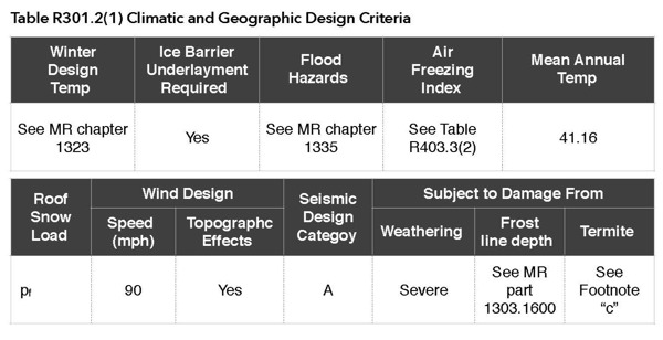
Minnesota specific design criteria for roof snow load, wind design, seismic, weathering, frost line depth, termite, winter design temp, ice barrier underlayment, flood hazard, air freezing index & mean annual temp are all contained in one table. Some column headings, however, will not be applicable throughout the entire state. Additionally, some Minnesota jurisdictions will need to specifically address column headings for Flood Hazards and Termites, if applicable to their local conditions.
Table R301.2(1) Climatic and Geographic Design Criteria
For SI: 1 pound per square foot= 0.0479 kPa, 1 mile per hour= 0.447 rnls.
a. Weathering may require a higher strength concrete or grade of masonry than necessary to satisfy the structural requirements of this code. The weathering column shall be filled in with the weathering index, such as “negligible,” “moderate,” or “severe,” for concrete as determined from the Weathering Probability Map [Figure R301.2(3)]. The grade of masonry units shall be determined from ASTM C 34, C 55, C 62, C 73, C 90, C 129, C 145, C 216, or C 652.
b. See Minnesota Rules, part 1303.1600 – Footing Depth for Frost Protection to verify whether the county requires Zone I or Zone II frost protection.
c. The jurisdiction shall fill in this part of the table to indicate the need for protection depending on whether there has been a history of local subterranean termite damage.
d. The jurisdiction shall fill in this part of the table with the wind speed from the basic wind speed map [Figure R301.2(4)A]. Wind exposure category shall be determined on a site-specific basis in accordance with section R301.2.1.4.
e. See Minnesota Rules, chapter 1322 – Table R403.5.17 Climate Data Design Conditions to verify by city.
f. The ground snow loads to be used in determining the design snow loads for buildings and other structures are given in Minnesota Rules, part 1303.1700 – Ground Snow Load to verify by county. The roof snow load is a uniform load on the horizontal projection of the roof.
g. See Minnesota Rules, chapter 1335, Flood Proofing Regulations.
h. In accordance with sections R905.2.7.1, R905.4.3.1, R905.5.3.1, R905.6.3.1, R905.7.3.1, and R905.8.3.1, where there has been a history of local damage from the effects of ice damming.
i. The jurisdiction shall fill in this part of the table with the 100-year return period air freezing index (BF-days) from Figure R403.3(2) or from the 100-year (99 percent) value on the National Climatic Data Center data table “Air Freezing Index-USA Method (Base 32~ F)” at www.ncdc.noaa.gov/oalfpsf.
j. The jurisdiction shall fill in this part of the table with the mean annual temperature from the National Climatic Data Center data table “Average Mean Temperature Index” at http://www.esrl.noaa.gov/psd/data/usclimate/tmp.state.19712000.climo
k. In accordance with section R301.2.1.5.
l. Assigned to allow the application of the least restrictive topographic provisions of the code.
Additional Resources for Table R301.2(1):
- For Minnesota’s Ground Snow Load and Roof Snow Load maps see http://www.dli.mn.gov/CCLD/PDF/bc_map_snowload.pdf or MN Rules Chapter 1303
- For Minnesota’s Frost Depth map, see http://www.dli.mn.gov/CCLD/PDF/bc_map_frost_depth.pdf or MN Rules Chapter 1303
- Flood Hazard requirements are covered under MN Rules Chapter 1335, see https://www.dli.mn.gov/ccld/PDF/SBC/1335.pdf
FIRE RESISTANT CONSTRUCTION
BAM Comments
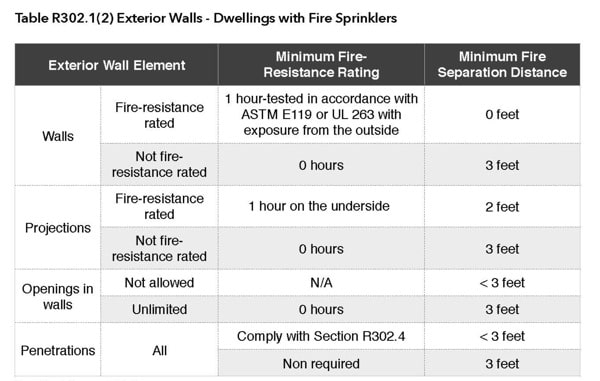
The minimum clearance to lot lines are reduced from 5 feet to 3 feet for unrated exterior walls when the dwelling unit is protected with a fire sprinkler.
Table R302.1(2) Exterior Walls – Dwellings with Fire Sprinklers
For SI: 1 foot= 304.8 mm
N/A =Not Applicable
a 1-hour on the underside equates to one layer of 5/8-inch type X gypsum sheathing.
Openings are not allowed.
R302.6, Dwelling/Garage Fire Separation
BAM Comments:
The table detailing the Dwelling/Garage Separation is modified to include the following:
- The wall-separation material on the garage side of the residence between the garage and the attic shall extend up to the roof sheathing or to the rafter blocking. This will not require sheet rock to be installed around the rafter block, but instead can stop at the rafter block, which will save time and extra materials.
- The garage ceiling or garage floor/ceiling can be used as a horizontal “fire wall” between the residence and garage instead of requiring a vertical “fire wall.”
- Any structural member that supports the garage ceiling or garage floor/ceiling when used as a horizontal fire separation must be protected with 1/2-inch gypsum board or equivalent material.
- Only garage walls that are parallel and less than 3 feet from the dwelling require the fire separation material to be installed. The requirement does not apply to garage walls that are perpendicular to the dwelling even if they are within 3 feet.
Table R302.6, Dwelling/Garage Fire Separation
| SEPARATION | MATERIAL |
| From the residence and attics | Not less than 1/2-inch gypsum board or equivalent applied to the garage side. Vertical separation between the garage and the residence attic shall extend to the roof sheathing or rafter blocking. |
| From all habitable rooms above the garage | Not less than 5/8-inch Type X gypsum board or equivalent |
| Structural members supporting floor/ceiling assemblies or garage ceiling used for separation required by this section | Not less than 1/2-inch gypsum board or equivalent applied to the garage side of structural members supporting the floor/ceiling assemblies or garage ceiling. Structural members include, but not limited to: walls, columns, beams, girders, and trusses. |
| Garages located less than 3 feet from a dwelling to unit on the same lot | Not less than 1/2 inch gypsum board or equivalent applied the interior side of exterior walls that are within this area. This provision does not apply to garage walls that are perpendicular to the adjacent dwelling unit wall. |
OPENING LOCATION
BAM Comments:
The minimum vertical clearance between a contaminant source and an outdoor air intake opening below has increased from 2 feet to 3 feet.
R303.5.1 Ventilation Intake Openings
Mechanical and gravity outdoor air intake openings shall be located a minimum of 10 feet from any hazardous or noxious contaminant, such as vents, chimneys, plumbing vents, streets, alleys, parking lots and loading docks, except as otherwise specified in this code. Where a source of contaminant is located within 10 feet of an intake opening, such opening shall be located a minimum of 3 feet below the contaminant source.
The exhaust from dwelling unit toilet rooms, bathrooms and kitchens shall not be considered as hazardous or noxious.
CEILING HEIGHT
BAM Comments:
The new definition for “crawl space” (less than 6 feet 4 inch ceiling height) is coordinate with other code changes that now permit the finishing of many existing basements that would have previously been considered crawl spaces.
For rooms with sloped ceilings, at least 50 percent of the required floor area of the room must have a ceiling height of at least 7 feet and no portion of the required floor area may have a ceiling height of less than 5 feet.
Bathrooms are required to have a minimum ceiling height of 6 feet 8 inches at the center of the front clearance area for water closets, bidets, or sinks.
R305.1 Minimum Height, New Buildings
Habitable space, hallways, bathrooms, toilet rooms, laundry rooms, and portions of basements containing these spaces shall have a ceiling height of not less than 7 feet (2134 mm).
The required height shall be measured from the finish floor to the lowest projection from the ceiling.
Exceptions:
- For rooms with sloped ceilings, at least 50 percent of the required floor area of the room shall have a ceiling height of at least 7 feet (2134 mm) and no portion of the required floor area may have a ceiling height of less than 5 feet (1524 mm).
- Bathrooms shall have a minimum ceiling height of 6 feet 8 inches (2032 mm) at the center of the front clearance area for water closets, bidets, or sinks. The ceiling height above fixtures shall be such that the fixture is capable of being used for its intended purpose. A shower or tub equipped with a shower head shall have a minimum ceiling height of 6 feet 8 inches (2032 mm) above a minimum area 30 inches (762 mm) by 30 inches (762 mm) at the showerhead.
R305.1.1 Basements, New Buildings
Portions of basements that do not contain habitable space, hallways, bathrooms, toilet rooms, and laundry rooms shall have a ceiling height of not less than 6 feet 8 inches (2032 mm).
Exception: Beams, girders, ducts, or other obstructions may project to within 6 feet 4 inches (1931 mm) of the finished floor.
R305.2 Alterations to Existing Building Basements
Alterations to portions of existing basements shall comply with the provisions of this section.
Alterations to existing basements needs to have a ceiling height of not less than 6 feet 4 inches, including beams, girders, ducts, or other obstructions.
Bathrooms will have a minimum ceiling height of 6 feet 4 inches at the center of the front clearance area (21 inches) for water closets, bidets, or sinks.
Alterations to existing basement stairways will have a minimum headroom in all parts of the stairway not less than 6 feet 4 inches.
R305.2.1 Minimum Ceiling Height, Existing Buildings
Alterations to existing basements or portions thereof shall have a ceiling height of not less than 6 feet 4 inches, including beams, girders, ducts, or other obstructions.
R305.2.1.1 Bathroom Plumbing Fixture Clearance
Bathrooms shall have a minimum ceiling height of 6 feet 4 inches at the center of the front clearance area for water closets, bidets, or sinks. A shower or tub equipped with a showerhead shall have a minimum ceiling height of 6 feet 4 inches above a minimum area 30 inches by 30 inches at the wall where the showerhead is placed. The ceiling may have slopes or soffits that do not infringe on the height required for the plumbing fixture.
R305.2.2 Minimum Stairway Headroom, Existing Buildings
Alterations to existing basement stairways shall have a minimum headroom in all parts of the stairway not less than 6 feet 4 inches measured vertically from the sloped line adjoining the tread nosing or from the floor surface of the landing or platform on that portion of the stairway.
Exception: Where the nosings of treads at the side of a flight extend under the edge of a floor opening through which the stair passes, the floor opening shall be allowed to project horizontally into the required headroom a maximum of 4-3/4 inches.
EMERGENCY ESCAPE AND RESCUE OPENINGS
BAM Comments:
The new exceptions to this section offer alternate methods of life safety by installing fire sprinklers instead of constructing and installing emergency escape and rescue openings.
R310.1 Emergency Escape and Rescue Required
Basements, habitable attics, and every sleeping room shall have at least one operable emergency escape and rescue opening. Where basements contain one or more sleeping rooms, emergency egress and rescue openings shall be required in each sleeping room, but not be required in adjoining areas of the basement. Where emergency escape and rescue openings are provided they shall have a sill height of not more than 44 inches (1118 mm) measured from the finished floor to the bottom of the clear opening. Where a door opening having a threshold below the adjacent ground elevation serves as an emergency escape and rescue opening and is provided with a bulkhead enclosure, the bulkhead enclosure shall comply with section R310.3. The net clear opening dimensions required by this section shall be obtained by the normal operation of the emergency escape and rescue opening from the inside. Emergency escape and rescue openings with a finished sill height below the adjacent ground elevation shall be provided with a window well in accordance with section R310.2. Emergency escape and rescue openings shall open directly into a public way, or to a yard or court that opens to a public way.
Exceptions:
- Basements used only to house mechanical equipment and not exceeding total floor area of 200 square feet (18.58 m2).
- Basements or basement bedrooms when the building is protected with an automatic sprinkler system installed in accordance with IRC section P2904 or NFPA 13D.
- Basements or basement bedrooms that comply with all of the following conditions:
- constructed prior to August 1, 2008;
- undergoing an alteration or repair; and
- the entire basement area, when all portions of the means of egress to the level of exit discharge, and all areas on the level of exit discharge that are open to the means of egress is protected with an automatic sprinkler system in accordance with IRC section P2904 or NFPA 13D.
BAM Comment:
R310.1.4 Exception is intended to permit the installation of window opening control devices on window units to provide window fall protection.
R310.1.4 Operational Constraints
Emergency escape and rescue openings shall be operational from the inside of the room without the use of keys, tools, or special know ledge.
Exception: Windows with approved window opening control devices and installed in accordance with ASTM F 2090. The devices shall not require the use of keys or tools to operate.
BAM Comment:
Replacement windows are exempt from the maximum sill height, minimum opening area, minimum opening width, and minimum opening height requirements. This change offers greater flexibility with replacement windows, while maintaining life safety.
R310.1.5 Replacement Windows
Replacement windows installed in buildings regulated by the International Residential Code shall be exempt from the maximum sill height requirements of section R310.1, including subsections R310.1.1, R310.1.2, and R310.1.32 if the replacement window is the manufacturer’s largest standard size window that will fit within the existing frame or existing rough opening. The replacement window shall be the same operating style as the existing window or a style that provides for an equal or greater window opening area than the existing window.
BAM Comment:
Foster care or licensed or registered daycare in the State of Minnesota must comply with sections R310.1.5 or R310.1.5.1, whichever is more restrictive.
R310.1.5.1 Licensed Facilities
Windows in rooms used for foster care or day care licensed or registered by the state of Minnesota shall comply with the provisions of section R310.1.5, or all of the following conditions, whichever is more restrictive:
- Minimum of 20 inches in clear opening width;
- Minimum of 20 inches in clear opening height;
- Minimum of 648 square inches (4.5 square feet) clear opening; and
- Maximum of 48 inches from the floor to the sill height.
STAIRWAYS
BAM Comments:
This requirement applies to stairs that serve as a means of egress from a dwelling. The exceptions in this section provide exclusions for stairs serving attics, crawl spaces, and access to plumbing, mechanical, or electrical equipment. These types of stairs are excluded because these stairs are not intended to serve as a means of egress from a dwelling.
R311.7.1 Stairways
All stairways serving a dwelling or accessory structure, or any part thereof, shall comply with this section. This shall include exterior stairs from a dwelling or garage to grade and those stairs serving decks, porches, balconies, sun rooms, and similar structures.
Exceptions:
- Stairs serving attics or crawl spaces.
- Stairs that only provide access to plumbing, mechanical, or electrical equipment.
BAM Comment:
R311.7.2 Exception #2 allows stairway headroom to be reduced to 6 feet 4 inches for stairs leading to a basement alteration, so that unfinished basements in existing buildings can be more easily finished.
R311.7.2 Headroom
The minimum headroom in all parts of the stairway shall not be less than 6 feet 8 inches measured vertically from the sloped line adjoining the tread nosing or from the floor surface of the landing or platform on that portion of the stairway.
Exceptions:
- Where the nosings of treads at the side of a flight extend under the edge of a floor opening through which the stair passes, the floor opening shall be allowed to project horizontally into the required headroom a maximum of 4-3/4 inches.
- The minimum headroom for existing buildings shall be in accordance with section R305.2.2.
WINDOW FALL PROTECTION
BAM Comments:
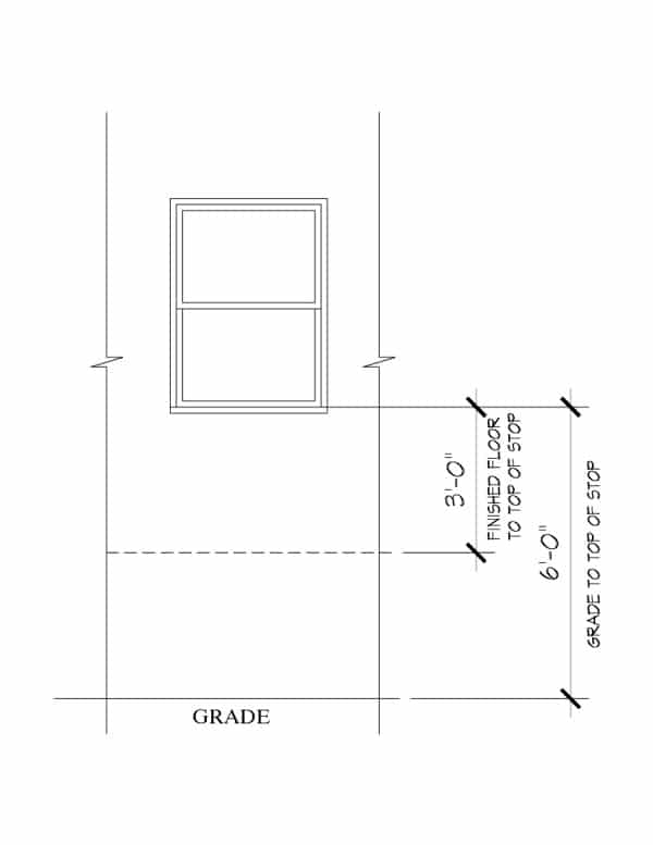
For windows where the lowest part of the opening is more than 72 inches above the finished grade or surface below, the lowest part of the opening must be 36 inches or higher from the interior finished floor. Window openings lower than 36 inches will be required to provide window fall prevention.
Pay particular attention in applications where you are meeting egress and sill height requirements.
R312.2 Fall Protection
Window fall protection shall be provided in accordance with sections R312.2.1 and R312.2.2.
R312.2.1 Window Sills
In dwelling units, where the lowest part of the opening of an operable window is located more than 72 inches (1829 mm) above the finished grade or surface below, the lowest part of the window opening shall be a minimum of 36 inches (914 mm) above the finished floor of the room in which the window is located. Operable sections of windows shall not permit openings that allow passage of a 4-inch diameter (102 mm) sphere where such openings are located within 36 inches (914 mm) of the finished floor.
Exceptions:
- Windows with openings that will not allow a 4-inch diameter (102 mm) sphere to pass through the opening when the window is in its largest opened position.
- Openings that are provided with window fall prevention devices that comply with ASTM F 2090.
- Windows that are provided with window opening control devices that comply with section R312.2.2.
- Replacement windows.
R312.2.2 Window Opening Control Devices
Window opening control devices shall comply with ASTM F 2090. The window opening control device, after operation to release the control device allowing the window to fully open, shall not reduce the minimum net clear opening area of the window unit to less than the area required by section R310.1.1.
AUTOMATIC FIRE SPRINKLER SYSTEMS
BAM Comments:
Automatic residential fire sprinkler systems will be required in all townhouses, two-family dwellings and in 4,500 square feet or larger single-family homes (4,500 sq. ft. floor area includes all floors and basements, excluding garages).
NOTE: See BAM’s Builder’s Fire Sprinkler Guide for more information.
Two-family dwellings (Twin Homes) and townhouses will also require a dry head sprinkler in the garage and dry heads every 20 lineal feet for covered patios, covered decks, covered porches, and similar structures attached to the home that are over 40 sq. ft. of floor area.
R309.5 Fire Sprinklers
Attached garages of two-family dwellings and townhouses shall be protected by fire sprinklers and installed in compliance with section R313.3.
BAM Comment: Previously only two-family dwellings and townhouses over 9250 square were required to install fire sprinklers.
R313.1 Townhouse Automatic Fire Sprinkler Systems
An automatic residential fire sprinkler system shall be installed in townhouses.
Exception: An automatic residential fire sprinkler system shall not be required when additions or alterations are made to existing townhouses that do not have an automatic residential fire sprinkler system installed.
R313.1.1 Design and installation. Automatic residential fire sprinkler systems for townhouses shall be designed and installed in accordance with IRC section P2904 or NFPA 13D.
R313.2 One- and Two-Family Dwellings Automatic Fire Systems
An automatic residential fire sprinkler system shall be installed in one-and two-family dwellings.
Exceptions:
- Detached one-family dwelling, less than 4500 square feet of floor area. Floor area shall include all floors and basements, excluding garages.
- An automatic residential fire sprinkler system shall not be required if additions, alterations, or repairs are made to existing buildings that do not have an automatic residential sprinkler system installed.
R313.2.1 Design and installation. Automatic residential fire sprinkler systems shall be designed and installed in accordance with IRC section P2904 or NFPA 13D.
R313.3 Installation Requirements
When an automatic sprinkler system is required in two-family dwellings, it shall be installed in accordance with IRC section P2904 or NFPA 13D.
Automatic sprinkler systems required in two-family dwellings and townhouse buildings shall be installed in accordance with the following:
- Attached garages are required to have one dry head sprinkler located within 5 lineal feet of each door installed in the common wall separating the dwelling unit and the attached garage;
- Attached covered patios, covered decks, covered porches, and similar structures are required to have automatic sprinklers with a minimum of one dry head for every 20 lineal feet (6.096 m) of common wall between the dwelling unit and the covered patio, covered deck, covered porch, or similar structure.
Exception: Attached roofs of covered patios, covered decks, covered porches, or similar structures that do not exceed 40 square feet (3,716 m2) of floor area.
R313.4 State-Licensed Facilities
One- and two-family dwellings and townhouse buildings containing facilities required to be licensed or registered by the state of Minnesota shall be provided with an automatic sprinkler system required by the applicable licensing provisions of that agency or according to this part, whichever is more restrictive.
SMOKE ALARMS
BAM Comment:
Section R314.3.1 provides two exceptions for remodeling work that does not require compliance with this section.
R314.3.1 Alterations, Repairs, and Additions
An individual dwelling unit shall be equipped with smoke alarms located as required for new dwellings when:
- alterations, repairs (including installation or replacement of windows or doors), or additions requiring a permit occur; or
- one or more sleeping rooms are added or created in existing dwellings.
Exceptions:
- Work involving the exterior surfaces of dwellings, such as the replacement of roofing or siding, or the addition of an open porch or deck, or chimney repairs.
- Installation, alteration, or repairs of plumbing, electrical, or mechanical systems.
BAM Comment: Wireless smoke alarms will meet the requirements of being interconnected.
R314.5 Interconnection
Where more than one smoke alarm is required to be installed within an individual dwelling unit in accordance with Section R314.3, the alarm devices shall be interconnected in such a manner that the actuation of one alarm will activate all of the alarms in the individual unit. Physical interconnection of smoke alarms shall not be required where listed wireless alarms are installed and all alarms sound upon activation of one alarm.
IRC Chapter 4: Foundations
Link to IRC Chapter 4: Foundations
CONCRETE FOOTINGS
BAM Comments:
The new footing specifications require the use of concrete that can withstand 5,000 pounds of force per square inch (“5,000 psi”). These new specifications will create a water separation plane between the soil and the building foundation.
Footnote “g” permits a concrete mixture that is 2,500 psi with an approved admixture (chemicals that can be added to concrete to change its moisture permeability), which provides a water and vapor resistance equivalent to that of 5,000 psi concrete.
Table R402.2, Minimum Specified Compressive Strength of Concrete
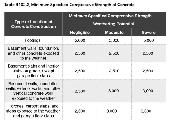
For SI: 1 pound per square inch= 6.895 kPa.
a.Strength at 28 days psi.
b.See Table R30,.2(1) for weathering potential.
c. Concrete in these locations that may be subject to freezing and thawing during construction shall be air-entrained concrete in accordance with Footnote d.
d. Concrete shall be air-entrained. Total air content (percent by volume of concrete) shall be not less than 5 percent or more than 7 percent.
e. See section R402.2 for maximum cementitious materials content.
f. For garage floors with a steel-troweled finish, reduction of the total air content (percent by volume of concrete) to not less than 3 Percent is permitted if the specified compressive strength of the concrete is increased to not less than 4,000 psi.
g. Compressive strength (fl ) of 2,500 psi, with an approved admixture that provides a water and vapor resistance at least equivalent to 5,000 psi concrete.
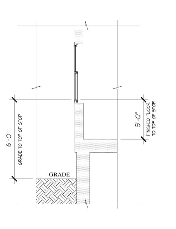
FOUNDATION WATERPROOFING
BAM Comment:
All concrete and masonry basement foundation walls are to be waterproofed. Dampproofing is no longer permitted.
R406.2 Concrete and Masonry Foundation Waterproofing
Exterior foundation walls that retain earth and enclose below grade interior spaces, floors and crawl spaces shall be waterproofed. Waterproofing shall be installed at a minimum from the top of the footing to the finished grade or in accordance with the manufacturer’s installation instructions. Walls shall be waterproofed in accordance with one of the following:
- 2-ply hot-mopped felts.
- 55 pound (25 kg) roll roofing.
- 6-mil (0.15 mm) polyvinyl chloride.
- 6-mil (0.15 mm) polyethylene.
- 40-mil (1 mm) polymer-modified asphalt
- 60-mil (1.5 mm) flexible polymer cement.
- 1/8-inch cement based, fiber reinforced, waterproof coating.
- 60-mil (1.5 mm) solvent free liquid applied synthetic rubber.
Exception: Organic solvent-based products such as hydrocarbons, chlorinated hydrocarbons, ketones, and esters shall not be used for ICF walls with expanded polystyrene form material. Use of plastic roofing cements, acrylic coatings, latex coatings, mortars, and pargings to seal ICF walls is permitted. Cold-setting asphalt or hot asphalt shall conform to Type C of ASTM D 449. Hot asphalt shall be applied at a temperature of less than 200° F (90° C).
All joints in membrane waterproofing shall be lapped and sealed with an adhesive compatible with the membrane.
IRC Chapter 5: Floors
Link to IRC Chapter 5: Floors
FIRE PROTECTION OF FLOORS
BAM Comments:
Installation of ½-inch gypsum board or 5/8-inch wood structural panel or approved equivalent is required on the underside of floor assemblies. If fire sprinklers are installed to protect the space below the floor assembly, this protection may not be required (nonmetallic fire sprinkler piping, not rated for exposure will need a thermal barrier).
An area not to exceed 80 sq. ft. can be left unprotected providing there is fireblocking installed along the perimeter of the unprotected area. The area around the furnace can be designated as the unprotected area.
See BAM’s Builder’s Fire Sprinkler Guide for more information.
R501.3 Fire Protection of Floors
Floor assemblies, not required elsewhere in this code to be fire-resistance rated, shall be provided with a 1/2-inch (12.7 mm) gypsum wallboard membrane, 5/8-inch (16 mm) wood structural panel membrane, or equivalent on the underside of the floor framing member.
Exceptions:
- Floor assemblies located directly over a space protected by an automatic sprinkler system in accordance with Section P2904, NFPA13D, or other approved equivalent sprinkler system.
- Floor assemblies located directly over a crawl space not intended for storage or fuel-fired appliances.
- Portions of floor assemblies can be unprotected when complying with the following: A. The aggregate area of the unprotected portions shall not exceed 80 square feet per story B. Fire blocking in accordance with Section R302.11.1 shall be installed along the perimeter of the unprotected portion to separate the unprotected portion from the remainder of the floor assembly.
- Wood floor assemblies using dimension lumber or structural composite lumber equal to or greater than 2-inch by 10-inch (50.8 mm by 254 mm) nominal dimension, or other approved floor assemblies demonstrating equivalent fire performance.
IRC Chapter 6: Wall Construction
Link to IRC Chapter 6: Wall Construction
TALL WALL OPENINGS
BAM Comments:
Table R602.3 .1 is amended by adding text to footnotes “c” and “d.” The amended footnotes provide additional prescriptive requirements regarding sheathing, fastening, bracing, and window or other openings in tall walls.
Footnote amendments:
c.. The exterior of the wall shall be continuously sheathed in accordance with one of the materials listed in items 32 to 38 in Table R602.3(1), including the prescribed fastening. All wall bracing requirements shall be in accordance with section R602.10.
d. Studs shall be continuous full height. Where studs do not extend full height due to a wall opening, full height studs shall be provided on each side of the opening, equal in number to the spacing of the required full height studs multiplied by half the width of the opening, plus one stud. Where multiple openings occur adjacent to one another, framing between openings shall include the total of all full height studs required for both openings combined.
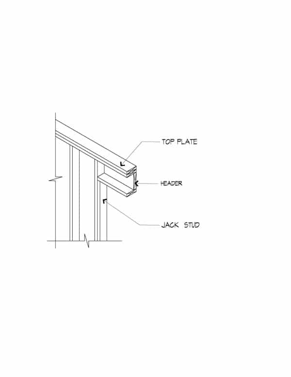
SINGLE MEMBER HEADERS
BAM Comment:
Single headers are allowed under limited loading conditions to increase energy efficiency and reduce the cost of construction.
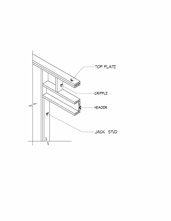
R602.7.1 Single Member Headers
Single headers shall be framed with a single flat 2-inch-nominal (51 mm) member or wall plate not less in width than the wall studs on the top and bottom of the header in accordance with Figures R602.7.1(1) and R602.7.1(2).
Table R602.7.1 Spans for Minimum No.2 Grade Single Header a, b, c, f
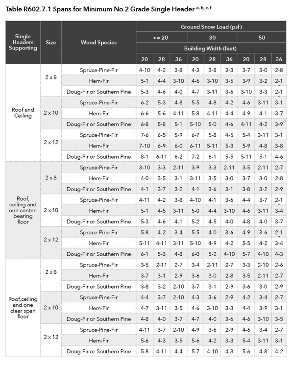
For SI: 1 inch=25.4 mm, 1 pound per square foot = 0.0479 kPa.
a. Spans are given in feet and inches.
b. Table is based on a maximum roof-ceiling dead load of 15 psf.
c. The header is permitted to be supported by an approved framing anchor attached to the full-height wall stud and to the header in lieu of the required jack stud.
d. The 20 psf ground snow load condition shall apply only when the roof pitch is 9:12 or greater. In conditions where the ground snow load is 30 psf or less and the roof pitch is less than 9:12, use the 30 psf ground snow load condition.
e. Building width is measured perpendicular to the ridge. For widths between those shown, spans are permitted to be interpolated.
f. The header shall bear on a minimum of one jack stud at each end.
WALL BRACING
BAM Comments:
This section has been extensively reorganized for clarity with each subsection covering a single topic in an effort to bring a user-friendly flow to the information. Wall bracing provides racking resistance against horizontal racking loads. Braced wall lines need to be indicated on the building plans.
The subsections are as follows:
- Braced wall lines [R602.10.1]. A straight line through the building plan to determine the amount and location of bracing required in each story level of a building.
- Braced wall panel [R602.10.2]. Braced wall panels are full-height sections of wall with no vertical or horizontal offsets.
- Required length of bracing [R602.10.3]
- Construction methods for braced wall panels [R602.10.4] Determines the construction methods and the bracing method mixing.
- Minimum length of a braced wall panel [R602.10.5]
- Construction of alternate braced wall panel methods [R602.10.6]
- Ends of braced wall lines with continuous sheathing [R602.10.7]
- Braced wall panel connections [R602.10.8]
- Braced wall panel support [R602.10.9]
Simplified Wall Bracing
BAM Comments:
This new section provides a simplified prescriptive approach for bracing wall lines that applies to many houses. Wall bracing is based on a rectangle drawn around the exterior of the building. The length of each side of the rectangle is limited to 60 feet while the ratio of the length to the width must be 3:1 or less. The exterior walls must be sheathed in either wood structural panels or structural fiberboard sheathing.
R602.12 Simplified Wall Bracing
Buildings meeting all of the conditions listed in items 1-8 shall be permitted to be braced in accordance with this section as an alternative to the requirements of Section R602.10. The entire building shall be braced in accordance with this section; the use of other bracing provisions of R602.10, except as specified herein, shall not be permitted.
- There shall be no more than two stories above the top of a concrete or masonry foundation or basement wall. Permanent wood foundations shall not be permitted.
- Floors shall not cantilever more than 24 inches (607 mm) beyond the foundation or bearing wall below.
- Wall height shall not be greater than 10 feet (2743 mm).
- The building shall have a roof eave-to-ridge height of 15 feet (4572 mm) or less.
- All exterior walls shall have gypsum board with a minimum thickness of 1/2 inch (12.7 mm) installed on the interior side fastened in accordance with Table R702.3.5.
- The structure shall be located where the basic wind speed is less than or equal to 90 mph (40 m/s), and the Exposure Category is A or B.
- The structure shall be located in Seismic Design Category A, B or C for detached one- and two-family dwellings or Seismic Design Category A or B for townhouses.
- Cripple walls shall not be permitted in two-story buildings.
IRC Chapter 7: Wall Covering
Link to IRC Chapter 7: Wall Covering
VAPOR RETARDERS
BAM Comments:
Vapor retarders are now classified by the ability of a material or assembly to limit the amount of moisture that passes through that material or assembly:
Class I: Permeance level of 0.1 perm or less (e.g. Sheet polyethylene)
Class II: Permeance level between 0.1 perm and 1.0 perm (e.g. Kraft-faced fiberglass batts or a “smart vapor retarder” [SVR])
Class III: Permeance level between 1.0 perm and 10 perms (e.g. Latex or enamel paint)
R702.7 Vapor Retarders
A Class I or II vapor retarder is required on the interior side of frame walls in Climate Zones 6 and 7. Class II vapor retarders are permitted only when specified on the construction documents.
R702.7.1 Class III Vapor Retarders
Class III vapor retarders shall be permitted where any one of the conditions in Table R702.7.1 is met.
Table R702.7.1 Class III Vapor Retarders
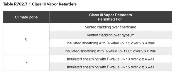
a. Spray foam with a minimum density of 2 lb/ft3 applied to the interior cavity side of wood structural panels, fiberboard, insulating sheathing or gypsum is deemed to meet the insulating sheathing requirement where the spray foam R-value meets or exceeds the specified insulating sheathing R-value. [R702.7.1]
WATER-RESISTIVE BARRIER
BAM Comments:
The water-resistive barrier needs to overlap required flashings not less than 2 inches. This would require that the flashing have a minimum 2-inch vertical leg to be overlapped. The 2-inch vertical flashing leg and water-resistive barrier overlap protects or limits wind driven water intrusion.
Also, the water resistive barrier will be installed continuous up to the underside of the rafter or truss top chord.
R703.2 Water-Resistive Barrier
One layer of No. 15 asphalt felt, free from holes and breaks, complying with ASTM D 226 for Type 1 felt or other approved water-resistive barrier shall be applied over studs or sheathing of all exterior walls. Such felt or material shall be applied horizontally, with the upper layer lapped over the lower layer not less than 2 inches (51 mm). The water-resistive barrier shall overlap the flashings required in section R703.8 not less than 2 inches (51 mm). Where joints occur in the water-resistive barrier or flashing, the joints shall be lapped not less than 6 inches (152 mm). The felt or other approved material shall be continuous up to the underside of the rafter or truss top chord and terminated at penetrations and building appendages in a manner to meet the requirements of the exterior wall envelope as described in section R703.1.
Exception: Omission of the water-resistive barrier is permitted in the following situations:
- In detached accessory buildings.
- Under exterior wall finish materials as permitted in Table R703.4.
- Under paperbacked stucco lath when the paper backing is an approved water-resistive barrier.
PLASTER CURING
BAM Comments:
The combined application of the first and second coat, sometimes called the “double-back” method, ensures an effective bond between the successive applications of the plaster and provides for a more uniform base-coat and better curing of the coats. The requirement that the second coat be applied no sooner than 48 hours after the application of the first coat would contradict current industry practice.
R703.6.4 Application
Each coat shall be kept in a moist condition for at least 48 hours prior to application of the next coat.
Exception: Applications installed in accordance with ASTM C 926: The second coat is permitted to be applied as soon as the first coat has attained sufficient rigidity to receive the second coat.
FLASHING
BAM Comments:
This section is reworded to clarify the requirements for flashing.
Flashing is now required at the intersection of the foundation and rim joist framing when the exterior wall covering does not lap the foundation insulation.
R703.8 Flashing
Approved corrosion-resistant flashing shall be applied shingle-fashion in such a manner as to prevent entry of water into the wall cavity or penetration of water to the building structural framing components. Self-adhered membranes used as flashing shall comply with AAMA711. The flashing shall extend to the surface of the exterior wall finish. Approved corrosion-resistant flashing shall be installed at all of the following locations:
- Exterior window and door openings. Flashing shall be installed at the head and sides of exterior window and door openings and shall extend to the surface of the exterior wall finish or to the water-resistive barrier for subsequent drainage. Flashing at exterior window and door openings shall be installed in accordance with at least one of the following: (a) the fenestration manufacturer’s installation and flashing instructions. When flashing is not addressed in the fenestration manufacturer’s instructions, it shall be installed in accordance with the flashing manufacturer’s instructions; (b) in accordance with the flashing design or method of a registered design professional; and (c) in accordance with other approved methods.
- At the intersection of chimneys or other masonry construction with frame or stucco walls, with projecting lips on both sides under stucco copings.
- Under and at the ends of masonry; wood, or metal copings and sills.
- Continuously above all projecting wood trim.
- Where exterior porches, decks, or stairs attach to a wall or floor assembly of wood-frame construction.
- At wall and roof intersections.
- At built-in gutters.
- Where exterior material meets in other than a vertical line.
- Where the lower portion of a sloped roof stops within the plane of an intersecting wall cladding in such a manner as to divert or kick out water away from the assembly in compliance with section R903.2.1.
- At the intersection of the foundation and rim joist framing when the exterior wall covering does not lap the foundation insulation.
IRC Chapter 9: Roof Assemblies
Link to IRC Chapter 9: Roof Assemblies
KICK-OUT FLASHING
BAM Comment:
Kick-out flashing on the roof needs to be a minimum of 2-1/2 inches long.
R903.2.1 Locations
Flashings shall be installed at wall and roof intersections, wherever there is a change in roof slope or direction and around roof openings. A kick-out flashing shall be installed to divert the water away from where the eave of a sloped roof intersects a vertical sidewall. The kick-out flashing on the roof shall be a minimum of 2-1/2 inches (63.5 mm) long. Where flashing is of metal,the metal shall be corrosion-resistant with a thickness of not less than 0.0 inch (0.5 mm) (No. 26 galvanized sheet).
R903.2.1.1 Existing Buildings and Structures
Kick-out flashings shall be required in accordance with section R903.2.1 when simultaneously re-siding and re-roofing existing buildings and structures.
Exception: Kick-out flashings are not required when only re-roofing existing buildings and structures.
Summary of Key Existing Building Changes
CEILING HEIGHT
R305.2.1 Minimum Ceiling Height, Existing Buildings
Alterations to existing basements or portions thereof shall have a ceiling height of not less than 6 feet 4 inches, including beams, girders, ducts, or other obstructions.
R305.2.2 Minimum Stairway Headroom, Existing Buildings
Alterations to existing basement stairways shall have a minimum headroom in all parts of the stairway not less than 6 feet 4 inches measured vertically from the sloped line adjoining the tread nosing or from the floor surface of the landing or platform on that portion of the stairway.
Exception: Where the nosings of treads at the side of a flight extend under the edge of a floor opening through which the stair passes, the floor opening shall be allowed to project horizontally into the required headroom a maximum of 4-3/4 inches.
EMERGENCY ESCAPE AND RESCUE OPENINGS
R310.1.5 Replacement Windows
Replacement windows installed in buildings regulated by the International Residential Code shall be exempt from the maximum sill height requirements of section R310.1, including subsections R310.1.1, R310.1.2, and R310.1.32 if the replacement window is the manufacturer’s largest standard size window that will fit within the existing frame or existing rough opening. The replacement window shall be the same operating style as the existing window or a style that provides for an equal or greater window opening area than the existing window.
SMOKE ALARMS
R314.3.1 Alterations, Repairs, and Additions
An individual dwelling unit shall be equipped with smoke alarms located as required for new dwellings when:
- Alterations, repairs (including installation or replacement of windows or doors), or additions requiring a permit occur; or
- One or more sleeping rooms are added or created in existing dwellings. Exceptions: 1. Work involving the exterior surfaces of dwellings, such as the replacement of roofing or siding, or the addition of an open porch or deck, or chimney repairs. 2. Installation, alteration, or repairs of plumbing, electrical, or mechanical systems.
FLASHING
R903.2.1.1 Existing Buildings and Structures
Kick-out flashings shall be required in accordance with section R903.2.1 when simultaneously re-siding and re-roofing existing buildings and structures.
Exception: Kick-out flashings are not required when only re-roofing existing buildings and structures.
REROOFING
R907.3 Recovering Versus Replacement
New roof coverings shall not be installed without first removing all existing layers of roof coverings where any of the following conditions exist:
- Where the existing roof or roof covering is water-soaked or has deteriorated to the point that the existing roof or roof covering is not adequate as a base for additional roofing.
- Where the existing roof covering is wood shake, slate, clay, cement or asbestos-cement tile.
- Where the existing roof has two or more applications of any type of roof covering.
Exceptions:
- Complete and separate roofing systems, such as standing-seam metal roof systems, that are designed to transmit the roof loads directly to the building’s structural system and that do not rely on existing roofs and roof coverings for support, shall not require the removal of existing roof coverings.
- Installation of metal panel, metal shingle and concrete and clay tile roof coverings over existing wood shake roofs shall be permitted when the application is in accordance with Section R907.4.
- The application of new protective coating over existing spray polyurethane foam roofing systems shall be permitted without tear-off of existing roof coverings.
- Where the existing roof assembly includes an ice barrier membrane that is adhered to the roof deck, the existing ice barrier membrane shall be permitted to remain in place and covered with an additional layer of ice barrier membrane in accordance with Section R905.
Still Have Questions?
Send your detailed energy code questions to BAM at info@bamn.org.
BAM will post the most commonly asked questions on BAM’s Code Q & A website page.