MINNESOTA ENERGY CODE GUIDE V.3
Copyright
Member Field Guide to the 2015 Minnesota Residential Energy CodeBuilders Association of Minnesota © Copyright 2017 All rights reserved. More information at info@bamn.org.
This document is meant to be used in conjunction with the 2012 International Energy Conservation Code ® (IECC) published by the International Code Council (ICC).
The IECC and sections from the IECC in this guide were reproduced with permission from the International Code Council. This Member Field Guide to the 2015 Minnesota Energy Code contains copyrighted material from the 2012 International Energy Conservation Code, which is a copyrighted work owned by the International Code Council, Inc. Without advance written permission from the copyright owner, no part of the International Residential Code may be reproduced, distributed or transmitted in any form or by any means, including, without limitation, electronic, optical or mechanical means (by way of example and not limitation, photocopying, or recording by or in an information storage revival system).
For more information on permission to copy material exceeding fair use, please contact:
Publications, 4051 West Flossmoor Road, Country Club Hills, IL 60478. Phone 1-888-ICC-SAFE (422-7233).
BAM is solely responsible for the content of this guide, not our project partners. This guide is intended as a training and reference tool for the residential construction industry. The Builders Association of Minnesota specifically disclaims any responsibility to any party for the content of this guide or any errors or omissions that it may contain. Summaries of code changes or specific code sections are provided for information only. Consult www.bamn.org to check for any errata or new information about Minnesota’s 2015 Residential Energy Code or this or other resources published by BAM.
Letter From the President
LETTER FROM THE PRESIDENT Dear Members of the Builders Association of Minnesota,
On behalf of the 2,300 members of the Builders Association of Minnesota (BAM), I am pleased to present the BAM Member Field Guide to the 2015 Minnesota Residential Energy Code. BAM’s mission is to help our members excel in the residential construction and remodeling industry. This guide is a tool to help members reach that goal.
This guide would not have been possible without the hard work of several dedicated members. These individuals served on code committees and councils and technical advisory committees, and generously gave of their time and talent to advocate for the industry and the best possible code for Minnesota.
I’d also like to thank you for your membership with the Association. These guides exist because of your membership, and they are a big part of the value of membership.
Sincerely,
Kurt Welker, 2017 President, Builders Association of Minnesota
Forward
Several resources were used to develop this guide and BAM wishes to extend sincere gratitude for the production of these guides for BAM’s membership:
Illustrations were generously donated by BAM Member George Cundy, Terrace Development and Design.
Production work was provided by Ed Von Thoma, Building Knowledge Inc.
Code guide review was provided by a group of dedicated BAM members. A big thank you to each member for their time, expertise, and dedication to excellence and the industry.
Introduction
The BAM Member Field Guide to the 2015 Minnesota Residential Energy Code was developed to help residential contractors, subcontractors, suppliers, local code officials, and others in the residential construction industry understand important code changes.
Building and remodeling permits applied for on or after February 14, 2014, will need to comply with the 2015 Minnesota Residential Energy Code, also known as Chapter 1322 of Minnesota Rules. The new code is based on the Residential Provisions of the 2012 International Energy Conservation Code (IECC) with amendments based on input from the Residential Energy Code Advisory Committee.
The commentary provided in this document is for reference only. Please refer to a copy of the 2012 IECC published by the ICC and the 2015 Minnesota Residential Energy Code published by the Minnesota Department of Labor and Industry for specific code language. Only specific sections of code language are included in their entirety in this guide.
This guide is intended as a training and reference tool for the residential construction industry. The Builders Association of Minnesota specifically disclaims any responsibility to any party for the content of this guide or any errors or omissions that it may contain. As always, the new construction and remodeling process is based on cooperation between the contractor and the local building official. Please keep in mind that these code changes are a summary and not all of the options presented in the code are included in this guide. The illustrations do not reflect all the references to actual code language. Check the original code language for precise requirements and options of specific code sections.
Note: the Minnesota Department of Labor and Industry will be publishing the 2015 Minnesota Building Code online and at that time BAM will provide a revised version of these member guides with links and reference to specific sections of the code. Look for version 2.0 in the coming months.
Overview
This guide will be most useful to you if you download a copy of the original code language. The link to the PDF can be downloaded directly from www.bamn.org/regulation.
In October, 2014 BAM posted a Member Guide: Top 20 Changes to the 2015 Minnesota Residential Energy Code on www.bamn.org/regulation. This Field Guide includes all of the information and illustrations from the Top 20 Changes.
If you have any comments or questions about this guide or Minnesota’s Residential 2015 Energy Code go to www.bamn.org/regulation and click on the Frequently Asked Questions sections to send BAM staff an e-mail message. Any updates to this guide will be posted on www.bamn.org/regulation as soon as they are available.
SCOPE
The 2015 Minnesota Residential Energy Code establishes minimum requirements for building and remodeling single-family, two-family, townhouses as well as Group R-2, R-3 and R-4 buildings three stories or less in height. The 2015 Minnesota Residential Energy Code is based on Chapters 2 – 5 of the Residential Provisions of the 2012 IECC. There are significant changes from IECC to the 2015 Minnesota Residential Energy Code. Fortunately the entire residential energy code will be available to download as a PDF document. Go to www.bamn.org/regulation to download a copy of the code.
APPLICABILITY
All new buildings and remodeling permits applied for on or after February 14, 2015, will need to comply with the 2015 Minnesota Residential Energy Code.
- Garages are exempt as are other parts of IRC buildings that do not enclose conditioned space, such as an unheated sunroom
- Additions must meet the requirements of the code but the existing dwelling does not have to be brought up to code.
- The exemptions for remodeling and repair projects are explained in the Changes for Remodelers section on page 38 of this guide
- Low energy use buildings are exempt from the entire 2015 Residential Energy Code
DEFINITIONS
The 2015 Residential Energy Code gives precise definitions to words and phrases used in the residential energy code chapter of the Minnesota State Building Code. If a word is used in the 2015 Residential Energy Code but is not specifically defined in Chapter 1322 the next place to look is in the International Residential Code’s Chapter 2: Definitions. Make sure that the version of the 2012 IRC you refer to includes the 2015 Minnesota specific amendments. If a word, term or phrase is not specifically defined in the 2015 Residential Energy Code or the Residential Building Code the next source to consult is posted version of the Merriam Webster on-line dictionary, which can be found at www.merriam-webster.com [R201.4 of the 2007 Minnesota State Residential Code].
Definitions help contractors and building officials determine what the intent of the code means. BAM staff members are often asked, “Why can’t the code just use normal words?”. When you a contractor thinks of an exterior window or door you probably don’t include everything on this list: “Skylights, roof windows, vertical windows (whether fixed or moveable); opaque doors, glazed doors, glass block; and combination opaque/glazed doors.” This list is the precise definition of FENESTRATION in the 2012 International Residential Code. Words and phrases that are specifically defined in the code usually reduce confusion when trying to understand the intent of a code section. But only if you know what the terms are defined as in the first place.
TECHNICAL STANDARDS REFERENCED IN THE ENERGY CODE
Definitions also allow abbreviations for technical organizations that set standards or the performance of certain products. For instance, section R402.4.3 of the code states that fenestration air leakage can be determined using NFRC 400. Referring to the National Fenestration Rating Council allows contractors and building officials to easily figure out if the products used will comply with the code according to third party testing. This organization is used only as an example, there are many other organizations that are referenced in the building and energy codes.
There are also many references to ASTM standards in the code. These requirements are there to protect contractors. Some are straightforward. For instance, exterior draining insulation used on the foundation walls has to meet ASTM C578, C612, or C1029. Ask your supplier or installer to document that their products meet one of these requirements for rigid extruded insulation board, mineral fiber drainage board, or spray urethane. These standards prevent your competitors from using products that are not intended for these applications.
Requiring that a product meets an ASTM standard is usually a yes/no answer. The product either meets a particular standard or it does not. One caution, beware when manufacturers claim they have tested a product according to a particular ASTM standard. Any manufacturer can have their products tested and this is no guarantee that they will perform to the standard. Make sure you purchase products with required ASTM Standards that have been tested and comply with the standard.
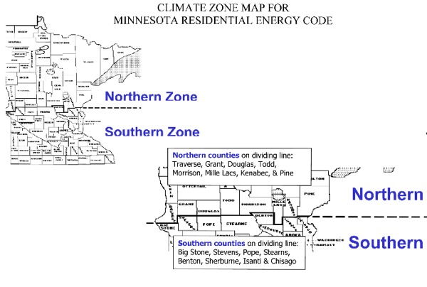
SOUTHERN/NORTHERN CLIMATE ZONE MAP
The energy code divides Minnesota into two climate zones: southern and northern. Some minimum R-value requirements are more stringent in the northern climate zone compared to the southern climate zone. The line dividing the northern and southern climate zones is exactly the same as the 5-foot/3.5 foot line in the State Building Code’s frost depth map.
Approving Alternate Methods With Your Local Building Official
The 2015 Minnesota Building Code allows local building officials the right to accept alternative materials, design and methods of construction. They also have the right to deny an alternative method that a contractor proposes. Alternative methods are frequently called alternate methods. A contractor must obtain prior permission from the building official before installing an alternate method.
1300.0110, Subp. 13. Alternative materials, design and methods of construction and equipment. The code is not intended to prevent the installation of any material or to prohibit any design or method of construction not specifically prescribed by the code, provided that any alternative has been approved. An alternative material, design, or method of construction shall be approved where the building official finds that the proposed design is satisfactory and complies with the intent of the code, and that the material, method, or work offered is, for the purpose intended, a least the equivalent of that prescribed in the code in quality, strength, effectiveness, fire resistance, durability, and safety. The details of any action granting approval of an alternate shall be recorded and entered in the files of the Department of Building Safety.
This provision in the Minnesota State Building Code allows new materials and methods to be used without the contractor having to wait for a new code to be adopted. Without this provision alternate materials and methods would violate the code and new products would go unused for several years. The national code cycle for developing new codes takes at least six years for the new code to be published. The state code adoption process may add years to the new code’s adoption date.
Using alternate methods without prior building official approval is like having your subcontractors not follow your plan specifications and having them tell you after installation, “But I didn’t think you’d care.”
Documentation and Labeling Required in the Code
IDENTIFYING PLANS AND SPECIFICATIONS
The following details must be included with the construction documents if applicable [1322.0103]:
- Insulation materials and their R-values
- Fenestration U-factors and SHGC’s
- Area-weighted U-factor and SHGC calculations
- Mechanical system design criteria
- Mechanical and service water heating system and equipment type, sizes and efficiencies
- Equipment and systems controls
- Fan motor horsepower (hp) and controls
- Duct sealing, and the location and insulation of ducts and pipes
- Lighting fixture schedule with wattage and control narrative
- Air sealing details
LABELING INSULATION
All thermal insulation must conform to Minnesota Rules, chapter 7640. This requirement actually protects contractors and homeowners from insulation products with untested, unsubstantiated R-value claims in on-site applications. The Minnesota Department of Commerce’s Office of Energy Security maintains a list of insulation manufacturers and suppliers that have registered their insulation product and are in compliance with state law:
http://mn.gov/commerce/energy/images/Insulation-Products-List.pdf
Crews installing blown or sprayed fiberglass insulation or cellulose insulation must provide the contractor a certificate that includes: initial installed thickness, settled thickness, settled R-value, installed density, coverage area, and number of bags installed. [R303.1.1]
Crews installing sprayed polyurethane foam (SPF) insulation must provide the contractor a certificate that includes: the installed thickness of the area covered and R-value of installed thickness. [R303.1.1]
Blown or sprayed roof/ceiling insulation requires insulation thickness markers facing the attic opening every 300 ft2 throughout the attic space. The markers have to be attached to the trusses or joists and marked with the initial installed thickness. The numbers on the markers have to be at least one inch high. [R303.1.1.1]
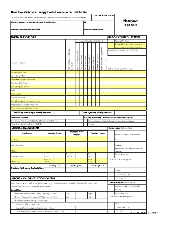
BUILDING CERTIFICATE FOR NEW CONSTRUCTION
Every new home requires a building certificate that lists R-values, insulation types, HVAC equipment specs, etc. This certificate has to be posted on or in the electrical distribution panel. Save a copy of this certificate in the house file. The information on this certificate may help you in the future. For instance it might help your legal team establish that a homeowner made modifications to the home that caused durability or performance problems.
BAM has created one-page template for you to use so you don’t need to fill out a different form for every municipality. See BAM www.bamn.org/regulation for a version you can download. There are two options an Excel version that you can customize with your logo and save changes to and a PDF version that can’t be saved but is useful if you are filling out the form by hand.
You are not required to use the BAM form, but you are required to post the information listed in R401.3.
Building Thermal Envelope
INSULATION AND FENESTRATION
There are four different ways to comply with the insulation requirements in the new residential energy code. They are described in the Building Thermal Envelope section (Section R402.1). The easiest and most straightforward way of complying with the code is to follow the requirements of Table R402.1.1 ~ Insulation and Fenestration Requirements by Component including all footnotes [Table R402.1.1]. Most builders and remodelers will use this method. Here are the four methods with a short description of each:
1. R-value computation (R402.1.2) Find the part of the building thermal envelope that needs insulating, find the correct R-value or U-value. Only the R-value of the insulation product can be used to meet the required minimum insulation level.
2. U-factor alternative (R402.1.3) This method allows you to count the entire U-factor of an entire assembly, not just the insulation. The U-factor is the inverse of the R-factor. These equivalent U-factors must be calculated by the manufacturer or another approved source. You can swap out any equivalent U-factor for an assembly for the minimum R-value found in Table R402.1.1.
3. Total UA alternative (R402.1.4) Hire an engineer or knowledgeable designer if you want to use this method because it involves using the ASHRAE Handbook of Fundamentals and calculating thermal bridging effects of framing materials.
4. The building official is permitted to approve specific computer software, worksheets, compliance manuals, and other similar materials that meet the intent of this code. If you already get a HERS Index rating for your homes the software can also generate a code compliance document.
BAM Comments:
Higher R-Values are more efficient than lower R-Values. Lower U-Factors are more efficient than higher U-Factors. To calculate the equivalent U-Factor of an insulation product take the inverse of the R-Value. To calculate the equivalent U-Factor of a building assembly as required in Table R402.1.1.2, add all of the R-Values of the individual components of the building assembly and take the inverse of the total.
Most builders will use the simple and straightforward R-value computation method, or as BAM likes to call it the “R-value Table.” In addition to the requirements to Table R402.1.1 on page 12 of the code, there are some additional rules that have to be followed to comply with the rest of Section N1102. We’ll start with the R-value Table and its footnotes. BAM’s comments are in italics below.
Table R402.1 Insulation and Fenestration Requirements by Component (a)
| Component | Southern Climate Zone (6) | Northern Climate Zone (7) |
| Fenestration U-Factor (b) | 0.32 | 0.32 |
| Skylight U-Factor (b) | 0.55 | 0.55 |
| Glazed Fenestration SHGC (b) | NR | NR |
| Ceiling R-Value (j) | 49 | 49 |
| Wood Frame Wall R-Value (f) | 20, 13+5 | 21 |
| Mass Wall R-Value (g), (h), (i) | 15/20 | 19/21 |
| Floor R-Value (e) | 30 | 38 |
| Foundation Wall (c), (i) | 15 | 15 |
| Slab R-Value & Depth (d) | 10, 3.5 ft | 10, 5 ft |
| Crawl Space Wall R-Value (c), (i) | 15 | 15 |
a. R-values are minimums. U-factors and SHGC are maximums. When insulation is installed in a cavity that is less than the label or design thickness of the insulation, the installed R-value of the insulation shall not be less than the R-value specified in the table.
BAM comments:
SHGC stand for Solar Heat Gain Coefficient. There are no requirements for maximum SHCG’s for windows and doors in Minnesota. However, you’ll still need to ask your window and door supplier for the SHGC since this number is required for the Building Certificate [1322.0103]. Having a SHGC for the windows and doors will help HVAC contractors size equipment more accurately.
b. The fenestration U-factor column excludes skylights. The SHGC column applies to all glazed fenestration.
c. See section R402.2.8.
d. Insulation R-values for heated slabs shall be installed to the depth indicated or to the top of the footing, whichever is less.
e. Or insulation sufficient to fill the framing cavity, R-19 minimum.
f. First value is cavity insulation, second is continuous insulation or insulated siding, so “13+5” means R-13 cavity insulation plus R-5 continuous insulation or insulated siding. If structural sheathing covers 40 percent or less of the exterior, the continuous insulation R-value is permitted to be reduced by no more than R-3 in the locations where structural sheathing is used to maintain a consistent total sheathing thickness.
BAM Comments:
In this context OSB and plywood are considered structural sheathing; fiberboard sheathing is not. Contact your rigid insulation supplier or manufacturer to help you determine what is needed to meet the wall bracing requirements of the IRC if you use this method of construction.
g. The second R-value applies when more than half the insulation is on the interior of the mass wall.
h. When using log-type construction for thermal mass walls the following applies: (1) a minimum of a 7-inch diameter log shall be used; and (2) the U-value of fenestration products shall be 0.29 overall on average or better.
i. See section R402.2.8. A minimum R-19 cavity insulation is required in wood foundation walls.
j. Roof/ceiling assemblies shall have a minimum 6-inch energy heel.
Fenestration U-Factor and Air Leakage Requirements
- Windows and doors have to meet an average U-factor of 0.32 or above in both climate zones [Table R402.1.1].
- Skylights are not included in this section or in the area weighted average for windows and doors [Table R402.1.1, footnote (b)].
- Up to 15 square feet of glazed fenestration per dwelling unit does not need to meet the U-factor requirement [R402.3.3].
- One opaque door assembly does not need to meet the U-factor requirement [R402.3.4]
- An area-weighted average of fenestration products can be used to determine the U-factor [R402.3.1]. This average does not include the exempted 15 square feet of glazing, one opaque door, or skylights as described above.
- Log homes require a maximum area weighted U-value of 0.29 [Table R402.1.1 footnote (h)].
- Windows and sliding glass doors must have an air infiltration rate of no more than 0.3 cubic foot per minute per square foot [1.5(L/s)/m2)], and swinging doors more than 0.5 cubic foot per minute per square foot [2.6(L/s)/m2)] [R402.4.3].
- Ask your window and door supplier to provide the proper documentation that their products have been properly tested meet this standard [R402.4.3].
- For sunrooms with thermal isolation and enclosing conditioned space, the maximum fenestration U-factor shall be 0.45.
You will need to calculate window-to-wall ratios to figure out the heat gain/loss and cooling loads required for the construction documents and building certificate. [3122.0103]
SKYLIGHT U-FACTOR
- Skylights have to meet a maximum 0.55 U-Factor. [Table R402.1.1]
- Skylights must have an air infiltration rate of no more than 0.3 cubic foot per minute per square foot [1.5(L/s)/m2)] [R402.4.3]. Ask your window and door supplier to provide the proper documentation that their products have been properly tested meet this standard.
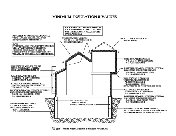
CEILING R-VALUE
Attic ceilings have to meet a minimum R-value of R-49 in both the Southern and Northern climate zones.
R-38 will be allowed to meet the requirement when the full height of uncompressed R-38 insulation extends over the exterior wall top plate at the eaves. [R402.2.1]
Vaulted ceilings have a limit of 500 square feet that are exempted from the R-49 minimum [R402.2.2]. The code calls vaulted ceilings, ceilings without attic spaces. If the roof/ceiling assembly does not allow sufficient space for R-49 then the minimum R-value is R-30; however only 500 square feet of ceiling area can use this exemption. If more than 500 square feet of vaults are included for a house you need to incorporate R-49 into the design or design these areas out of your plans. [R402.2.2 and Table R402.1.1]
Attic insulation thickness markers are required for blown or sprayed roof/ceiling insulation. [R303.1.1.1]
Roof/ceiling assemblies shall have a minimum 6-inch energy heel. [R402.1.1 item j]
Walls & Floors
WOOD FRAME WALLS
Wood frame wall insulation is R-20 or R-13+R-5 for the Southern climate zone. The first value is cavity insulation, the second is continuous exterior insulation, so “R-13 + R-5” means R-13 cavity insulation plus R-5 continuous insulation. Where structural sheathing covers 40 percent or less of the exterior, continuous exterior insulation R-value can be reduced by no more than R-3 to maintain a consistent total sheathing thickness.
Wood frame wall insulation is R-21 for the Northern climate zone.
[R402.1.1]
The rim-joist must now meet the R-value, air barrier and vapor retarder requirements of the wood framed wall.
MASS WALLS (ICFs & LOG HOMES)
Mass walls must meet a minimum R-value of R-15/20 in the Southern climate zone and R-19/21 in the Northern climate zone. The second R-value applies when more than half the insulation is on the interior of the mass wall. Mass walls are defined in the code as concrete block, concrete, insulated concrete forms (ICF), masonry cavity, brick (not brick veneer), earth, solid timber or logs. Ask your supplier for information on the R-value of their products.
Log homes have two additional requirements: (1) logs must be at least 7 inches in diameter and (2) the average U-factor of the fenestration products must be a minimum of 0.29 [Table R402.1.1, footnote (h)].
FLOORS
Floor R values are R-30 for the Southern climate zone and R-38 for the Northern climate zone. If the framing cavity is not sufficiently deep, insulate full depth to R-19 minimum. [Table R402.1.1] Floors include cantilevered bay windows, heated sunrooms, and bonus rooms over garages. Floor insulation must be installed tight to the subfloor decking.
SLABS
In the Southern climate zone unheated slabs have to be insulated with a minimum R-10 to a depth of 3.5 feet. In the Northern climate zone the R-10 must be installed a minimum of 5 feet deep [Table R402.1.1]. Insulation R-values for heated slabs need to be installed to the depth indicated or to the top of the footing, whichever is less. [Table R402.1.1, footnote (d)]
FOUNDATION WALLS: OTHER THAN TRADITIONAL POURED CONCRETE MASONRY BLOCK
- Permanent wood foundations must be designed and installed in accordance with American Forest & Paper Association Permanent Wood Foundation Design Specification.
- Frost-protected shallow foundations shall meet the requirements of R403.3 in the IRC.
- Insulating concrete form materials shall meet the requirements of R611 in the IRC.
FOUNDATION WALLS: POURED CONCRETE OR MASONRY BLOCK
Basement insulation requirements are increased. Minimum R-values for basements are now R-15 with a minimum of R-10 insulation required to be installed on the exterior of the wall.
Interior insulation, other than closed cell spray foam, shall not exceed R-11.
Exception: R-10 continuous insulation on the exterior of each foundation wall will be permitted to comply with this code if the tested air leakage rate required in section R402.4.1.2 does not exceed 2.6 air changes per hour and the total square feet between the finished grade and the top of each foundation wall does not exceed 1.5 multiplied by the total lineal feet of each foundation wall that encloses conditioned space. Interior insulation, other than closed cell spray foam, cannot exceed R-11. See footnote c to Table R402.2.1.
Foundation walls meeting the 2015 Residential Energy Code’s foundation wall insulation performance option are also allowed [R402.1.1.8]. Since this option requires certification from an engineer licensed in Minnesota this option is not explained in this guide.
WATERPROOFING NOT DAMP-PROOFING
Damp-proofing foundation walls is no longer permitted. Waterproofing is a building code requirement, however it does relate to the strategies for meeting the foundation wall insulation requirements and we note them here for the sake of clarity.
Cast-in-place concrete and masonry block foundation walls must be waterproofed according to IRC section R406 and the following requirements:
1. The waterproofing will extend from the top interior wall edge, across the top of the wall, and down the exterior wall face to the top of the footing. If a full width, closed-cell material is installed to create a seal between the sill plate and the top of the foundation wall, this installation will meet the requirements for the top of the wall waterproofing.
2. If the walls are exposed to the exterior environment, the waterproofing system must have a rigid, opaque, and weather-resistant protective covering to prevent degradation of the waterproofing system. The protective covering must cover the exposed waterproofing and extend a minimum of 6 inches below grade. The protective covering system must be flashed in accordance with IRC section R703.8. [R402.1.1]
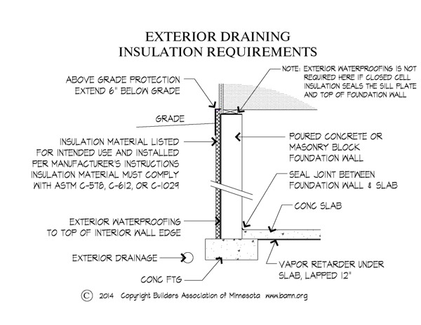
Exterior Draining Foundation Insulation Requirements
Any insulation assembly installed on the exterior of the foundation walls and on the perimeter of slabs-on-grade that permits water drainage needs to:
- Be made of water-resistant materials manufactured for that intended use;
- Be installed according to the manufacturer’s installation instructions;
- Comply with either ASTM C578, C612, or Cl029, as applicable; and
- Have a rigid, opaque, and weather-resistant protective covering to prevent the degradation of the insulation’s thermal performance. The protective covering shall cover the exposed exterior insulation and extend a minimum of 6 inches (152 mm) below grade. The insulation and protective covering system shall be flashed in accordance with IRC section R703.8.
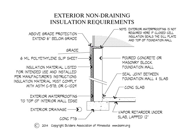
Exterior Non-Draining Foundation Insulation Requirements
Any insulation assembly installed on the exterior of the foundation walls or on the perimeter of slabs-on-grade that does not permit bulk water drainage needs to:
- Be made of water-resistant materials manufactured for that intended use;
- Be installed according to the manufacturer’s installation instructions;
- Comply with either ASTM C578 or C1029, as applicable;
- Be covered with a 6-mil polyethylene slip sheet over the entire exterior surface; and
- Have a rigid, opaque, and weather-resistant protective covering to prevent degradation of the insulation’s thermal performance. The protective covering shall cover the exposed exterior insulation and extend a minimum of 6 inches below grade. The insulation and protective covering system shall be flashed in accordance with IRC section R703.8.
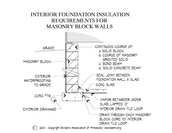
Interior Foundation Insulation Requirements
Any insulation assembly installed on the interior of foundation walls needs to meet the following requirements:
- Masonry foundation walls shall be drained through each masonry block core to an approved interior drainage system.
- If a frame wall is installed, it shall not be in direct contact with the foundation wall.
- The insulation assembly shall comply with the interior air barrier requirements of section R402.4.
- The insulation assembly shall comply with section R402.1.1.5, R402.1.1.6, or R402.1.1.7, as applicable.
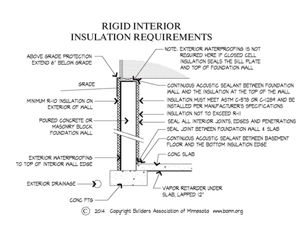
Rigid Interior Insulation Requirements
Rigid interior insulation needs to comply with ASTM C578 or ASTM C1289 and the following requirements:
1. For installation:
A. the insulation shall be in contact with the foundation wall surface;
B. vertical edges shall be sealed with acoustic sealant;
C. all interior joints, edges, and penetrations shall be sealed against air and water vapor penetration;
D. continuous acoustic sealant shall be applied horizontally between the foundation wall and the insulation at the top of the foundation wall; and
E. continuous acoustic sealant shall be applied horizontally between the basement floor and the bottom insulation edge.
2. The insulation shall not be penetrated by the placement of utilities, fasteners, or connectors used to install a frame wall, With the exception of through penetrations.
3. Through penetrations shall be sealed around the penetrating products.
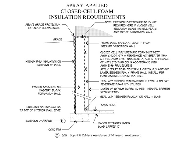
Spray-Applied Interior Foam Insulation Requirements
Spray-applied interior foam insulation will comply with the following:
1. Closed-cell foam:
A. The foam shall comply with ASTM C1029 and have a permeance not greater than 0.8, in accordance with ASTM E96 procedure A, and a permeance of not less than 0.3, in accordance with ASTM E96 procedure B.
B. The foam shall be sprayed directly onto the foundation wall surface. There shall be a l-inch minimum gap between the foundation wall surface and any framing.
C. The insulation surface shall not be penetrated by the placement of utilities, fasteners, or connectors used to install a frame wall, with the exception of through penetrations.
D. Through penetrations shall be sealed around the penetrating products.
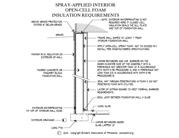
2. Open-cell foam:
A. The foam shall be sprayed directly onto the foundation wall surface. There shall be a l-inch minimum gap between the foundation wall surface and any framing.
B. The insulation surface shall not be penetrated by the placement of utilities, fasteners, or connectors used to install a frame wall, with the exception of through penetrations.
C. Through penetrations shall be sealed around the penetrating product.
D. A vapor retarder and air barrier shall be applied to the warm-in-winter side of the assembly with a permeance not greater than 1.0, in accordance with ASTM E96 procedure A, and a permeance not less than 0.3, in accordance with ASTM E96 procedure B.
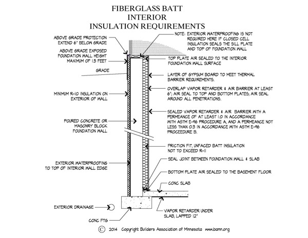
Fiberglass Batt Interior Insulation Requirements
Fiberglass batt insulation will comply with the following:
1. The above-grade exposed foundation wall height will not exceed 1.5 ft.
2. The top and bottom plates shall be air sealed to the foundation wall surface and the basement floor.
3. A vapor retarder and air barrier will be applied to the warm in winter side of the wall with a permeance not greater than 1.0 in accordance with ASTM E96 procedure A and a permeance not less than 0.3 in accordance with ASTM E96 procedure B meeting the following requirements:
A. the vapor and air barrier will be sealed to the framing with construction adhesive or equivalent at the top and bottom plates and where the adjacent wall is insulated;
B. the vapor and air barrier will be sealed around utility boxes and other penetrations; and
C. all seams in the vapor and air barrier will be overlapped at least 6 inches and sealed with compatible sealing tape or equivalent.
Sunrooms & Minimum Insulation R Values
SUNROOMS
If the sunroom encloses conditioned space it must meet the insulation requirements of this code. If the sunrooms is thermally isolated, and also encloses conditioned space, the following exceptions to the insulation requirements of this code will apply:
1. The minimum ceiling insulation R-value is R-24; and
2. The minimum wall R-value will be R-13. Wall(s) separating a sunroom with a thermal isolation from conditioned space need to meet the building thermal envelope requirements of this code.
If the sunroom is “thermally isolated” and isn’t heated then there are no requirements for the windows, doors, walls, ceilings, and floors.
SUMMARY OF MINIMUM INSULATION R VALUES
Air Barriers & Vapor Retarders
AIR BARRIERS & VAPOR RETARDERS: WHAT’S THE DIFFERENCE?
Air barriers block air movement. Without blocking air movement air barriers are ineffective.
Vapor retarders are not called ‘vapor barriers’ for a reason. Vapor retarders do not need to block all vapor to be effective, they just need to slow vapor movement over most of the wall or other building assembly where they are used.
This is a critical distinction in the designing and building of durable wall assemblies.
Many contractors and building officials confuse the intent of an air barrier and a vapor retarder. This confusion probably happens because sealed polyethylene (poly) sheets are the most common vapor retarder and air barrier used by Minnesota contractors. Unsealed poly can serve as a vapor retarder, but not as an air barrier. Once the poly is sealed it can also serve as an air barrier. There are many other types of products that can serve as either a vapor retarder, an air barrier or both depending on their properties. The important thing is to understand is that both a vapor retarder and an air barrier need to be installed where the building code requires them.
VAPOR DIFFUSION MANAGEMENT
Vapor retarders are a building code requirement, however it does relate to the strategies for meeting the wall insulation requirements and we note them here for the sake of clarity:
Vapor retarders are now classified by the ability of a material or assembly to limit the amount of moisture that passes through that material or assembly:
Class I: Permeance level of 0.1 perm or less (e.g. Sheet polyethylene)
Class II: Permeance level between 0.1 perm and 1.0 perm (e.g. Kraft-faced fiberglass batts or a “smart vapor retarder” [SVR])
Class III: Permeance level between 1.0 perm and 10 perms (e.g. Latex or enamel paint)
A Class I or II vapor retarder is required on the interior side of frame walls in Climate Zones 6 and 7. Class II vapor retarders are permitted only when specified on the construction documents. [R702.7]
Exceptions:
Basement walls.
Below grade portion of any wall.
Construction where moisture or its freezing will not damage the materials.
Table: Class III Vapor Retarders Permitted For the Following
Climate Zone / Class III Vapor Retarders Permitted For (a):
Climate Zone 6 / Vented cladding over fiberboard
Climate Zone 6 / Vented cladding over gypsum
Climate Zone 6 / Insulated sheathing with R-value => 7.5 over 2 x 4 wall
Climate Zone 6 / Insulated sheathing with R-value => 11.25 over 2 x 6 wall
Climate Zone 7 / Insulated sheathing with R-value => 10 over 2 x 4 wall
Climate Zone 7 / Insulated sheathing with R-value => 15 over 2 x 6 wall
a. Spray foam with a minimum density of 2 lb/ft3 applied to the interior cavity side of wood structural panels, fiberboard, insulating sheathing or gypsum is deemed to meet the insulating sheathing requirement where the spray foam R-value meets or exceeds the specified insulating sheathing R-value. [R702.7.1]
AIR LEAKAGE
The building thermal envelope must be constructed to limit air leakage.
Table: Air Barrier and Insulation Installation Criteria
| COMPONENT | CRITERIA |
| Air barrier and thermal barrier | A continuous air barrier shall be installed in the building envelope. Exterior thermal envelope contains a continuous air barrier. Breaks or joints in the air barrier shall be sealed. Air-permeable insulation shall not be used as a sealing material. |
| Ceiling/attic | The air barrier in any dropped ceiling/soffit shall be aligned with the insulation and any gaps in the air barrier sealed. Access openings, drop down stair or knee wall doors to unconditioned attic spaces shall be sealed. |
| Walls | Corners and headers shall be insulated and the junction of the foundation and sill plate shall be sealed. The junction of the top plate and top of exterior walls shall be sealed. Exterior thermal envelope insulation for framed walls shall be installed in substantial contact and continuous alignment with the air barrier. Knee walls shall be sealed. |
| Windows, skylights and doors | The space between window/door jambs and framing and skylights and framing shall be sealed. |
| Rim joists | Rim joists shall be insulated and include the air barrier. |
| Floors(including above-garage and cantilevered floors) | Insulation shall be installed to maintain permanent contact with underside of subfloor decking. The air barrier shall be installed at any exposed edge of insulation. |
| Crawl space walls | Where provided in lieu of floor insulation, insulation shall be permanently attached to the crawlspace walls. Exposed earth in unvented crawl spaces shall be covered with a Class I vapor retarder with overlapping joints taped. |
| Shafts, penetrations | Duct shafts, utility penetrations, and flue shafts opening to exterior or unconditioned space shall be sealed. |
| Narrow cavities | Batts in narrow cavities shall be cut to fit, or narrow cavities shall be filled by insulation that on installation readily conforms to the available cavity space. |
| Garage separation | Air sealing shall be provided between the garage and conditioned spaces. |
| Recessed lighting | Recessed light fixtures installed in the building thermal envelope shall be air tight, IC rated, and sealed to the drywall. |
| Plumbing and wiring | Batt insulation shall be cut neatly to fit around wiring and plumbing in exterior walls, or insulation that on installation readily conforms to available space shall extend behind piping and wiring. |
| Shower/tub on exterior wall | Exterior walls adjacent to showers and tubs shall be insulated and the air barrier installed separating them from the showers and tubs. |
| Electrical/phone box on exterior walls | The air barrier shall be installed behind electrical or communication boxes or air sealed boxes shall be installed. |
| HVAC register boots | HVAC register boots that penetrate building thermal envelope shall be sealed to the subfloor or drywall. |
| Fireplace | An air barrier shall be installed on fireplace walls. Fireplaces shall have gasketed doors. |
More Information:
Air sealing details can be found at these websites. Make sure to check with your local building official to confirm if a specific technique meets the intent of the 2015 Minnesota Residential Energy Code
Oikos® Green Building Source Library:
http://www.oikos.com/library/airsealing/index.html
EPA Energy Star Thermal Enclosure System Rater Checklist Guidebook:
http://www.energystar.gov/ia/partners/bldrs_lenders_raters/downloads/Energy_Star_v3_TERC_Guidebook.pdf
AIR LEAKAGE TESTING
Blower door tests are used to measure home air leakage rates. Homes will need to be tested and verified as having an air leakage rate of not exceeding 3 air changes per hour at a pressure of 50 Pascals (ACH50).
The building official can require testing to be conducted by an approved third party. A written report of the results of the test will be signed by the party conducting the test and provided to the building official.
The testing should take place after all the exterior penetrations have been made and sealed. [R402.4.1.2]
During testing:
1.Exterior windows and doors, fireplace and stove doors need to be closed, but not sealed, beyond the intended weatherstripping or other infiltration control measures;
2. Dampers including exhaust, intake, makeup air, backdraft and flue dampers need to be closed, but not sealed beyond intended infiltration control measures;
3. Interior doors, if installed at the time of the test, need to be open;
4. Exterior doors for continuous ventilation systems and heat recovery ventilators need to be closed and sealed;
5. Heating and cooling systems, if installed at the time of the test, will be turned off; and
6. Supply and return registers, if installed at the time of the test, will be fully open.
Mechanical Systems: Duct Sealing
Ducts, air handlers, and filter boxes need to be sealed. Duct seams must be fastened using sheet metal screws (or compression straps for flex duct) before being sealed. UL Standard 181 regulates both tape and mastics for air ducts.
Exceptions:
1. Air-impermeable spray foam products will be permitted to be applied without additional joint seals.
2. Where a duct connection is made that is partially inaccessible, three screws or rivets shall be equally spaced on the exposed portion of the joint to prevent a hinge effect.
3. Continuously welded and locking-type longitudinal joints and seams in ducts operating at static pressures less than 500 Pa pressure classification will not require additional closure systems.
Duct tightness shall be verified by either of the following:
1. Post-construction test: Total leakage shall be less than or equal to 4 cfm per 100 square feet of conditioned floor area when tested at a pressure differential of 25 Pa across the entire system, including the manufacturer’s air handler enclosure. All register boots will be taped or otherwise sealed during the test.
2. Rough-in test: Total leakage shall be less than or equal to 4 cfm per 100 square feet of conditioned floor area when tested at a pressure differential of 25 Pa across the system, including the manufacturer’s air handler enclosure. All registers will be taped or otherwise sealed during the test. If the air handler is not installed at the time of the test, total leakage shall be less than or equal to 3 cfm per 100 square feet of conditioned floor area.
Exception: The total leakage test is not required for ducts and air handlers located entirely within the building thermal envelope.
BAM Comments:
It is extremely difficult to meet a total duct system leakage rate less than 4cfm per 100 sq. ft. of conditioned floor area. Confirm with the building code official that your strategies for locating ducts entirely within the building thermal envelope meet the requirements of the code. Ducts in exterior walls and cantilevered floor systems over unconditioned spaces may be considered within the building thermal envelope if the construction techniques employed by the builder are approved by the building code official.
SEALED AIR HANDLER
Air handlers must have a manufacturer’s designation for an air leakage of no more than 2 percent of the design air flow rate when tested in accordance with ASHRAE 193. [R403.2.2.1]
BUILDING CAVITIES
Building framing cavities must not be used as ducts or plenums. [R403.2.3]
Ducts are defined in the energy code as: “A tube or conduit utilized for conveying air. “
BAM Comments:
It has been common practice to use panned floor joists and wall cavities as return-air pathways. However, field testing demonstrates that these type of return systems are extremely leaky, rarely meeting industry performance standards and a major source of comfort complaints. To meet this new code requirement use only approved duct materials that meet Minnesota code requirements for your duct systems. Consult with your HVAC contractor to optimize your duct system layouts for your home plans. This may require modifications to your designs to accommodate supply and return chases, fully ducted system designs and to locate the duct work within the thermal envelope.
Mechanical Systems: Mechanical Ventilation
All residential building types will need a mechanical ventilation system that is balanced within +/- 10% of the system’s design capacity for the continuous and total mechanical ventilation requirements. Exhaust only systems will not meet the requirements of balanced ventilation.
At least one supply and one return duct has to be installed in all unfinished basements and conditioned crawlspaces for new construction. These supply and return ducts have to be separated by one-half the diagonal dimension of the basement.
Outdoor air intakes and exhausts need to have automatic or gravity dampers that close when the ventilation system is not operating.
Kitchen and bath fans that are not included as part of the mechanical ventilation system are exempt from these requirements.
ALTERATIONS
Alterations to existing buildings are exempt from the balanced mechanical ventilation system requirements [R403.5.1]
TOTAL VENTILATION RATE
The total ventilation rate (TVR) is based on a calculation based on the number of bedrooms and square footage of the conditioned space, including the basement and conditioned crawl spaces or the ventilation rates from Table R403.5.2.
Total ventilation rate (cfm) = (0.02 x square feet of conditioned space)+ (15 x (number of bedrooms+ 1)) [R403.5.2]
CONTINUOUS VENTILATION RATE
The Continuous ventilation rate (CVR) is a minimum of 1/2 the total ventilation rate. The CVR must not be less than 40 cfm and will provide a continuous average cfm rate for every 1-hour period.
The portion of the ventilation system that is intended to be continuous may have automatic cycling controls to provide the average flow rate for each hour. [R403.5.3]
INTERMITTENT VENTILATION RATE
Intermittent ventilation rate is the difference between the total ventilation rate and the continuous ventilation rate. [R403.5.4]
BAM Comments:
According to table R403.5.2 a 3,000 square foot house (including the basement) with three bedrooms would have a total ventilation rate of at least 120 cfm, a continuous ventilation rate of at least 60 cfm and an intermittent ventilation rate of a least 60 cfm.
BALANCED AND HRV/ERV SYSTEMS
All balanced systems must be balanced so that the air intake is within 10 percent of the exhaust output.
A heat recovery ventilator (HRV) or energy recovery ventilator (ERV) will meet either:
1. the requirements of HVI Standard 920, 72 hours minus 13°F (-10°C) cold weather test;
2. or certified by a registered professional engineer and installed per manufacturer’s installation instructions.
An HRV or ERV installed to comply with both the continuous and total ventilation rate requirements will meet the rated design capacity of the continuous ventilation rate specified in section R403.5.3 under low capacity and meet the total ventilation rate specified in section R403.5.2 under high capacity.
Exception: The balanced system and HRV/ERV system may include exhaust fans to meet the intermittent ventilation rate. Surface mounted fans shall have a maximum 1.0 sone per HVI Standard 915. [R403.5.5]
BAM Comments:
HRV/ERV systems may be the most practical method of meeting the balanced ventilation requirements. It is conceptually possible to meet the requirements of balanced ventilation using a combination of fans, mechanical dampers, controls, etc., however these customized solutions may be more difficult and expensive in practice than using a HRV/ERV system. Consult your HVAC contractor to discuss the best option for the home you are building.
BALANCED SYSTEM INSTALLATION REQUIREMENTS
The mechanical ventilation system and its components need to be installed according to the Minnesota Mechanical Code, Minnesota Rules, chapter 1346, the equipment manufacturer’s installation instructions and the following [R403.5.6]:
Air Distribution/Circulation
The energy code requires not only mechanical ventilation but also a requirement that fresh air is delivered to each habitable space. This can be accomplished by a forced air circulation system, separate duct system, or individual inlets. [R403.5.6.1]
Forced Air Circulation Systems
Outdoor air supplied through a forced air circulation system must use one of the following methods:
A. Outdoor air supply not ducted to the forced air system, controls will need to provide an average circulation flow rate each hour of not less than 0.15 cfm per square foot of the conditioned floor area; or
B. Outdoor air supply ducted to the forced air system, the mixed air temperature must not be less than the heating equipment manufacturer’s installation instructions. Controls will need to provide an average flow rate not less than 0.075 cfm per square foot of conditioned floor area.
Directly Ducted and Individual Room Inlets
Not all houses have forced air heating/cooling systems. In this case a balanced ventilation system can be installed with its own dedicated ducting system. Outdoor air supplied directly to habitable spaces with an airflow of 20 cfm or greater, needs to be designed and installed to temper incoming air to not less than 40°F ( 4 °C) measured at the point of distribution into the habitable space.
Airflow Verification
All mechanical ventilation system airflows greater than 30 cfm at the building exhaust and intake needs to be tested and verified. The airflow verification results will be made available to the building official upon request.
FANS
Fans used as part of the mechanical ventilation system, need to deliver the designed air flow at the point of exhaust or intake as determined by section R403.5.2 and according to HVI Standard 916. [R403.5.7]
Fans need to be designed and certified by the equipment manufacturer to be capable of continuous operation at the maximum fan-rated cfm. Surface mounted fans used to comply with the continuous ventilation requirement of the mechanical ventilation system need to have a maximum 1.0 sone, according to HVI Standard 915. Fans used to comply with the intermittent ventilation requirement of the mechanical ventilation system must have a maximum 2.5 sone, according to HVI Standard 915. Mechanical ventilation system fans must meet the efficacy requirements of Table R403.5.1.
Exception to sone requirements: Sone requirements do not apply to forced air circulation systems and remotely mounted fans. If the remotely mounted fan is not in a habitable space and there are at least 4 feet of ductwork between the fan and grille, then the fan sone rating will be 2.5 sone or less. Where mechanical ventilation fans are integral to tested and listed HVAC equipment, the fans need be powered by an electronically commutated motor.
MULTI-FAN SYSTEMS
Two or more fans in a dwelling unit sharing a common duct must be equipped with a backdraft damper to prevent recirculation of exhaust air into another room. [R403.5.8]
CONNECTION TO FORCED AIR CIRCULATION SYSTEMS
Either the outdoor air supply or the exhaust air may be connected directly to the forced air circulation system, but not both. To meet the mechanical ventilation system requirements, the air duct must be installed according to the manufacturer’s installation instructions. [R403.5.9]
Exception: Both the outdoor air and exhaust air duct may be connected to the forced air circulation system only if controls are installed to operate the forced air circulation system when the mechanical ventilation system is operating or other means are provided to prevent short circuiting of ventilation air in accordance with the manufacturer’s recommendations.
DAMPERS
The mechanical ventilation system supply and exhaust ducts will need accessible backflow dampers installed to minimize flow to or from the outdoors when the ventilation system is off. [R403.5.10]
INTAKE OPENINGS
Exterior air intake openings need to be accessible for inspection and maintenance. Intake openings shall be located according to the Minnesota Mechanical Code, Minnesota Rules, chapter 1346, and will be covered with a corrosion-resistant screen of not less than 1/4-inch (6.4 mm) mesh. Intake openings shall be located at least 12 inches (305 mm) above adjoining grade level. [R403.5.11]
Exception: Combination air intake and exhaust hoods may be approved by the building official when specifically allowed by the equipment manufacturer’s installation instructions.
FILTRATION
All mechanically supplied outdoor air will have a filter with a designated minimum efficiency of MERV 4 as defined by ASHRAE Standard 52.2. The filter location shall be prior to the air entering the thermal conditioning components, blower, or habitable space. The filter needs to be installed so it is readily accessible and facilitates regular service. [R403.5.12]
NOISE AND VIBRATION
Mechanical ventilation system components shall be installed to minimize transmission of noise and vibration. The equipment manufacturer’s installation instructions shall be followed and any materials provided by the equipment manufacturer for installation shall be used. In the absence of specific materials or instructions, vibration dampening materials, such as rubber grommets and flexible straps, shall be used when connecting fans and heat exchangers to the building structure. Isolation duct connectors shall be used to mitigate noise transmission. [R403.5.13]
CONTROLS
Balanced mechanical ventilation system controls shall comply with all the following:
1. When the mechanical ventilation system is not designed to operate whenever the forced air circulation system is operating, the mechanical ventilation system shall incorporate an accessible back flow damper to prevent flow from the outside when the mechanical ventilation system is off.
2. Controls shall be compatible with the mechanical ventilation system, its components, and the manufacturer’s installation and operating instructions.
3. Controls shall be installed to operate the mechanical ventilation system as designed.
4. Each control shall be readily accessible to occupants and shall be labeled to indicate the control’s function.
[R403.5.14]
LABELING
All intake and exhaust ventilation outlets must be labeled on the exterior of the building. This makes it easier to differentiate between the intake and exhaust outlets and the equipment or appliance they serve. [R403.5.15]
DOCUMENTATION
Provide homeowner with documentation for operation and maintenance instructions of the mechanical ventilation system. [R403.5.16]
CLIMATE DESIGN CONDITIONS
Size HVAC equipment according to the ACCA Manual S or an equivalent method, based on the building’s heating and cooling load calculations by using ASHRAE Handbook of Fundamentals or the ACCA Manual J. [R403.5.17]
- Oversizing of heating equipment must not exceed 40 percent of the calculated load requirements.
- Oversizing of cooling equipment must not exceed 15 percent of the calculated load requirements.
- Use Table R403.5.17 to determine the design conditions for the city where you are building.
Materials, Systems and Equipment
HOT WATER PIPE INSULATION
R-3 pipe insulation on most types of hot water piping (i.e. if the piping is under slabs, to the kitchen, runs over 20’ for 1/2” diameter pipe, 3/4” in diameter or larger, etc).
R403.4.2 Hot water pipe insulation
Insulation for hot water pipe with a minimum thermal resistance (R-value) of R-3 shall be applied to the following:
- Piping larger than 3/4 inch nominal diameter.
- Piping serving more than one dwelling unit.
- Piping from the water heater to kitchen outlets.
- Piping located outside the conditioned space.
- Piping from the water heater to a distribution manifold.
- Piping located under a floor slab.
- Buried piping.
- Supply and return piping in recirculation systems other than demand recirculation systems.
- Piping with run lengths greater than the maximum run lengths for the nominal pipe diameter given in Table R403.4.2.
All remaining piping shall be insulated to at least R-3 or meet the run length requirements of Table R403.4.2.
TABLE R403.4.2 MAXIMUM RUN LENGTH (feet)a
| Nominal Pipe Diameter of Largest Diameter Pipe in the Rum (inch) | 3/8 | 1/2 | 3/4 | > 3/4 |
| Maximum Run Length | 30 | 20 | 10 | 5 |
For SI: 1 inch = 25.4 mm, 1 foot 304.8 mm.
a. Total length of all piping from the distribution manifold or the recirculation loop to a point of use.
Electrical Power and Lighting Systems
ENERGY EFFICIENT LIGHTING
75% percent of the bulbs in permanently installed light fixtures must be high efficacy. This requirement applies to indoor and outdoor fixtures, including accessory structures and garages. High efficacy bulbs are: 60 lumens/W for lamps over 40W; 50 lumens/W for lamps over 15W to 40W; 40 lumens/W for lamps 15W or less.
R404.1 Lighting equipment:
A minimum of 75 percent of the lamps in permanently installed lighting fixtures shall be high-efficacy lamps or a minimum of 75 percent of the permanently installed lighting fixtures shall contain only high efficacy lamps.
Exception: Low-voltage lighting shall not be required to utilize high-efficiency lamps.
Changes for Remodelers
This section summarizes the main energy code changes that affect remodelers. Refer to the original code language for all instances where additions, remodels, alterations and repairs might be affected by the new 2015 Residential Energy Code.
ADDITIONS, ALTERATIONS, RENOVATIONS OR REPAIRS
The following existing building projects are exempt from the energy code requirements provided they do not increase the energy use of the home:
- Storm windows over existing windows
- Glass-only replacements in an existing sash and frame
- Exposed, existing ceiling, wall or floor cavities if already filled with insulation
- Where existing roof, wall or floor cavity is not exposed
- Reroofing and residing
- Replacement of existing exterior doors
- Lighting alterations to permanently installed light fixtures if:
- Less than 50% of luminaries in a space are replaced
- Only bulbs and ballasts within existing luminaries are replaced
- The alterations do not increase the installed lighting power
REMODELED BASEMENTS
You still DON’T need insulation, an air barrier, or a vapor retarder on foundation walls or crawl space walls when you finish an unfinished basement or remodel an existing finished basement if the home was permitted before June 1, 2009. Remodeled basements in homes permitted after June 1, 2009 will need to meet the insulation requirements of the new code.
Since adding insulation in a wet basement can cause serious moisture problems, remodelers need to adjust their insulation and water management strategy to each individual remodeling job. So for an older basement, you have five options:
- Leave the existing insulation system in place and finish the walls.
- Remove the existing insulation system and add a new system of your choosing.
- Add an insulation system of your choice to an unfinished basement wall.
- Leave the basement uninsulated.
- Don’t take the remodeling job in cases where the homeowner won’t pay for a finished basement that will be both warm and reliably dry.
In summary, build a foundation system that works for your homeowner. You can certainly use the new construction wall foundation specifications or modify them to fit the needs of the specific home or create your own system.
Still Have Questions?
Send your detailed energy code questions to BAM at info@bamn.org.
BAM will post the most commonly asked questions on BAM’s Code Q & A website page.